With today’s technology, inertia matching isn’t the requirement it once was to design a servo-based machine. However, when tuning a system to minimise the inertia mismatch, wider requirements remain in order to optimise an application’s motion control performance. From motor sizing through to minimising mechanical compliance, a comprehensive approach to motion design will enhance system stability and precision.
Is Inertia Matching Still Essential?
Gerard Bush, motion engineer at Intelligent Motion Control (INMOCO), explains.
To size a servo system, previously, it was always considered essential to match the inertia of the motor with the load. Matching the inertia, that is the resistance to changes in rotational motion, ensures the necessary torque to achieve the required acceleration and deceleration. It also enables the right dynamism and stability, and optimises efficient power transfer.
These rules remain true, yet the problem of aiming for a 1:1 inertia match ratio would often result in a much larger motor than might otherwise be required, or it would require a gearbox. Either approach would create a more expensive, and less efficient outcome. Instead, today’s technologies involving faster processors and advanced control algorithms enables correction of the inertia mismatch.
Servo Drive Technology and Control Loops
Thanks to a closed loop servo system, which continuously monitors and adjusts based on feedback, the control and stability of position, velocity, and current/torque loops are enhanced. The servo drive tunes the control loops to operate with the required bandwidth, determining how fast the servo can adjust in response to commands. The servo drive also impacts the level of stiffness, optimising precision and control of the system by managing the response to deformation or displacement when force is applied. As a result of these improvements, the development of the servo drive significantly reduced the need for inertia matching.
Modelling and Simulation for System Response
The introduction of brushless motor technology and low mass, torque-dense NeFeB magnets, reduced motor inertia further still, however this extended the inertia mismatch. In response, the development of increased processing power, as well as higher resolution feedback devices, allowed the servo controller to create accurate mathematical modelling and simulation of system responses. Today, these tools enable motion engineers and machine designers to create interactive analytics by showing the precise detail of the mechanical system. Crucially, this data indicates how to address performance limitations.
An extended look at the detail of interaction across a mechanical system is also important to address compliance. This challenge represents the natural springiness of the mechanisms between the driven load and the motor that creates delayed response times, leading to reduced system bandwidth.
When a large inertia mismatch is introduced to the system, such as a small, high torque motor connected to an exceptionally large load via a coupling device, the compliance problem is magnified. When the motor quickly applies torque, the large load hesitates to respond due to its high inertia; the delay is a result of coupling compliance between the motor and load that introduces windup before the load begins to move. As the load finally synchronises with the motor, the large inertia causes overshoot of the target speed, resulting in the motor adjusting to slow down. When the system adjusts the overspeed of the inertia, the target speed is again passed, triggering the motor to adjust once more. This causes a continued cycle of repeated adjustment that creates resonance and an unstable system.
Understanding the Compliance Challenge
Most mechanical systems can be mathematically modelled and simulated using various excitation frequencies to identify the response point where resonance occurs. However, the bandwidth of a system can never exceed the initial anti-resonance point. In fact, the higher the compliance, the lower the frequency of the initial resonance point, that reduces bandwidth accordingly. When the driven load is directly coupled to the motor to minimise compliance, the mismatch is mitigated, increasing the initial resonance frequency and creating a higher bandwidth system.
Mathematical models show that the ultimate solution for a higher bandwidth and cost-effective system is to increase the mechanical stiffness and reduce total system inertia. Consider a direct drive solution where the load is directly coupled to the motor with near zero compliance; in cases like this, precisely controlling the system with high bandwidth can be achieved with inertia mismatches as high as 30:1. As direct drive solutions are not suited to all applications, compliant links will inevitably be introduced. However, advanced analytical tools, such as the bode plot, can readily identify the compliant elements that reduce system performance.
Motion Engineering for High Inertia Applications
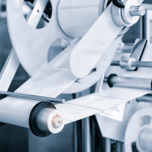
Applications often characterised by a high inertia mismatch can include printing and labelling, as well as various robot designs. Although inertia mismatch is no longer the main challenge, resolving the imbalance requires careful specification across a range of aspects, from motor sizing, through to tuning and analytics of the control algorithms, and mechanical architecture.
Assistance in specifying a system is particularly useful for machines with an inherent inertia mismatch. With comprehensive application sizing and best practices in designing a stiff mechanism, this can achieve a high-performance motion system capable of higher bandwidths, improved move and settle times, and robust dynamic control.


