British industry is adopting more and more sophisticated automation as it strives to build a competitive manufacturing edge over its global competitors. Here, Gerard Bush at servo motion specialists, INMOCO lifts the curtain on motion control for articulated robot arms.
Automation engineers are increasingly called upon to provide two-dimensional positioning systems, say for packing multiple products into a tray. Normally, a Cartesian mechanism is used for this with two perpendicular linear actuators working in unison, one providing the x-axis movement, the other the y-axis.
But in some applications, a jointed, articulated robot arm provides a better solution. They look intriguingly like a human arm, with a shoulder joint and an elbow joint. But programming one to be able to move to positions defined by XY coordinates can seem a bit daunting for a first timer!
The mathematical discipline used to calculate the necessary movements of the upper and lower arms is known as ‘motion kinematics.’ While this may seem complicated, it is, in fact, based on some simple trigonometric principles.
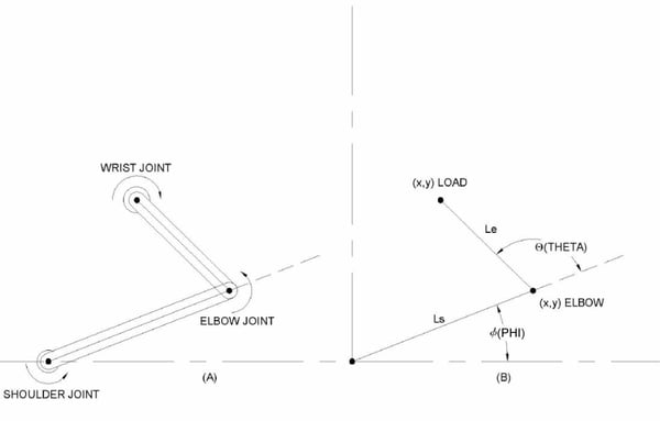
Articulated robot arms are often referred to as SCARA (Selective Compliant Assembly Robot Arm) robots, or PUMA (Programmable Universal Manipulation Arm) robots. In the most common SCARA robot configurations, there are four axes of motion, although only two, the shoulder rotation and the elbow rotation, contribute to the positioning of the load point in the XY plane (see below). The third axis is the wrist (or load point), which is often a tool or end effector, and the fourth axis moves the entire arm up and down.

How do the two main motion actuators, the shoulder joint and the elbow joint, position the end effector? To answer this, we must calculate the ‘forward kinematics’ of the arm, i.e. equations which translate the combined shoulder and elbow rotations into the X and Y coordinates of the load point.
The equations, which denote the shoulder-connected segment as length Ls, the elbow-connected segment as Length Le, the shoulder angle as phi (Φ), and the elbow angle as theta (Θ), are given below:

(eq. 1)

(eq. 2)
This is basic trigonometry. If we know the lengths of the upper and lower arm parts and the angles of the two joints, we can calculate the X and Y axis coordinates of the end effector.
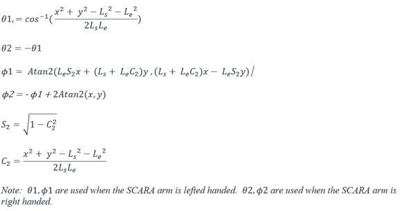
But there is an obvious problem here – the mathematical procedure is the reverse of the practical situation. What we actually know is the desired XY coordinates; what we want to calculate is the two joint angles. So we need to use ‘inverse kinematics’, and this is more complicated.
To begin with, there are always two ways to get to every location in the motion plane – with the arm cranked to the left or with the arm cranked to the right. Nevertheless, still using basic trigonometry, we can derive the equations for the two joint angles (phi and theta) given X and Y. They are given below.

Dynamics
The above equations are used to calculate positions for the load point, but when it moves from one position to another, the natural trajectory is not a straight line but a curve. This is due to the effect of the combined rotation of the two joints.
The curved trajectory leads to extra energy consumption compared to a straight line and can make tracking the load point more difficult. Thus, a straight line motion, while not always strictly necessary, is usually preferable.
In order to achieve a straight line motion, the speed of rotation of both joints must be constantly varied. This is, in fact, the primary challenge of controlling non-Cartesian mechanisms: to continuously calculate and reset the speed of each joint’s rotation to produce direct line travel.
Fortunately, there are a number of ways to do this. For instance, some motion controllers allow you to download equations and have sufficient computing power to perform inverse kinematic calculations on the fly.
Another approach, and perhaps the most common method used until relatively recently, is to break the curved trajectory into discrete steps and use standard motion control programs to convert each one into a straight line. Even just a few steps will dramatically improve the straightness, and if you break the movement into dozens or hundreds of pieces, very smooth motions will be achieved. The main downside of this segmented approach is that it requires a lot of work from the supervisory software program.
The third approach, now becoming increasingly popular, uses software lookup tables to perform ‘reference frame conversions’ on-the-fly. Here’s how it works. You program in the starting and ending XY coordinates, plus several intermediate coordinates that are on the straight line trajectory. Offline, the software does all the calculations to move the end effector through each point in turn. Execution of the profile by the motion controller then happens in real time, via a simple and fast lookup operation.
Lookup tables could require fairly powerful controllers. In fact, a table that contained every possible movement would take up an impractical amount of memory. So the practical answer is to use only a specific library of moves that are needed for the application. Thus, most motion systems have instructions for moves such as “extend straight out”, “retract straight in”, or “move from station #3 to station #8”, etc…
This library method is useful and convenient, but has certain limitations. The main one is that you must create a separate table for each application. Another is that you cannot use the ‘feedforward’ techniques employed by servo engineers working with Cartesian systems to compensate for load inertia.
Summary
The fundamental mathematics of control for SCARA robot arms and similar systems is described by forward and inverse kinematics. But these equations can be complex and create challenges for managing path execution. There are techniques to manage this complexity, of which translation tables that convert XY points to phi and theta angular movements are increasingly the most popular.
This branch of motion control mathematics can seem daunting, but with practice can be mastered. And it is always a good idea to seek the assistance of the experts from your motion control provider – after all, they practise the techniques day in and day out.


